FEA / AIRCRAFT STRUCTURES
How does a wing box carry shear?
I modelled a three-cell, thin-walled box beam in Abaqus and compared its response with hand calculations. The study traced shear flow through the webs and located the shear centre under a 6 kN vertical load.
01 / STRUCTURE
Three cells. Ten webs. One load path.
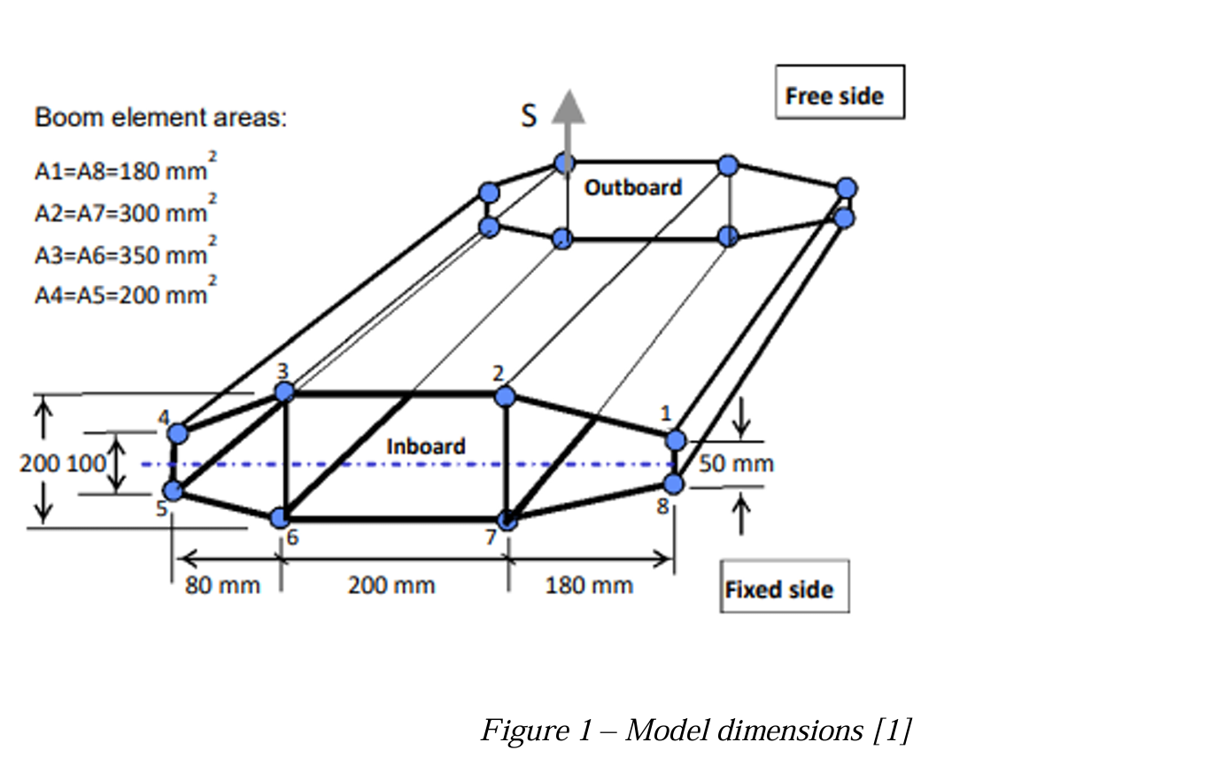
The beam represents a simplified aircraft wing structure. Its three closed cells, varying web thicknesses and two internal diagonal webs create a statically indeterminate load path.
The cross-section is defined by eight boom locations connected by ten webs. The beam length is 1,800 mm; web thicknesses range from 5 to 20 mm, with the 3–6 and 2–7 diagonals at 20 mm.
Those internal members couple the cells and play a major role in how the structure resists twisting.
02 / ABAQUS MODEL
Shell model, checked for convergence
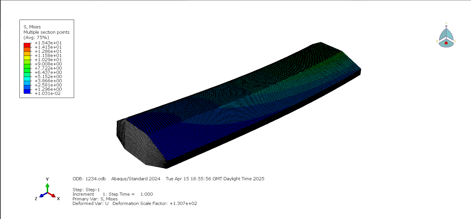
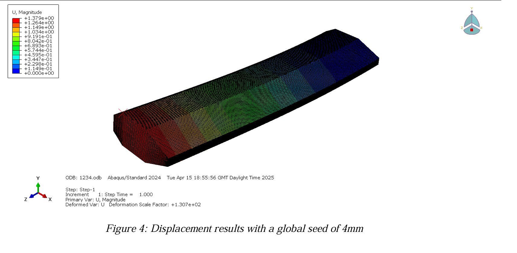
I used four-node reduced-integration shell elements (S4R) to capture the thin walls’ membrane, bending and shear response. One end was fixed; a 6 kN vertical load was distributed across the end web at the free side.
03 / MESH CONVERGENCE
When does the answer settle?
I refined the global mesh and tracked maximum von Mises stress. The result changed less between the 5 mm and 4 mm meshes than in earlier refinements, so 4 mm was selected for the remaining analysis.
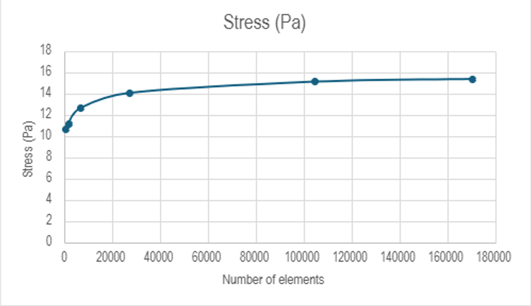
Unit note: the supplied chart labels stress as Pa; the report discussion and Abaqus contour legend use MPa. The chart is shown as provided.
04 / FEM VS HAND CALCULATION
Check the load path two ways
Hand calculations using boom idealisation gave a useful independent check. They agreed closely with Abaqus for both internal diagonal webs, while other webs exposed the limits of the simplified assumptions.
| Web | Abaqus shear flow | Hand calculation | Difference |
|---|---|---|---|
| 2–7 · internal diagonal | 16.28 N/mm | 16.49 N/mm | 1.3% |
| 3–6 · internal diagonal | 8.21 N/mm | 8.17 N/mm | 0.4% |
Where they diverged: the simplified method differed by more than 700% for webs 3–4 and 5–6, where the FEM shear flow was near zero. That result highlighted how boom idealisation and uniform-web-flow assumptions can miss local behaviour in a multi-cell section.
05 / SHEAR CENTRE
Where can the load act without twist?
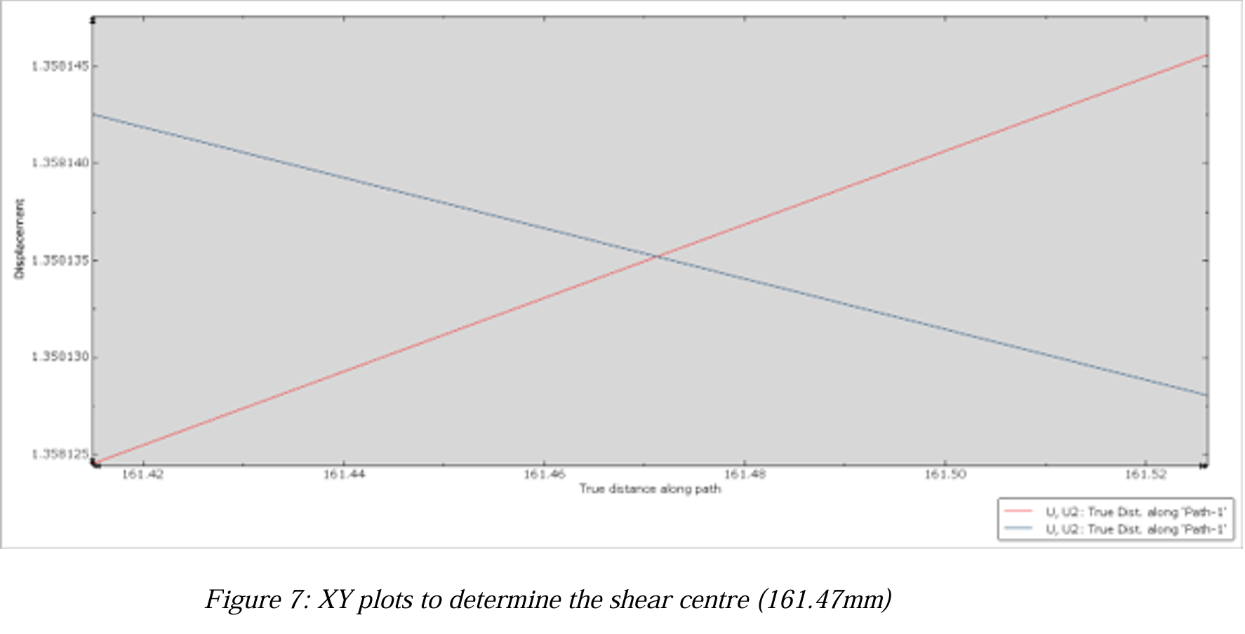
The shear centre was located from displacement-path data. It identifies the point through which a transverse load must pass to avoid inducing a twisting response in this section.
The strongest result wasn’t just a stress contour. It was showing where the finite element model and hand calculations agreed—and where their assumptions stopped matching the structure.
Scope / static, linear-elastic model with ideal geometry; no plasticity, fatigue, thermal or aerodynamic loading. This coursework model demonstrates analysis and validation methods, not a flight-certified structural design.